deutsche Version
HF-Messtechnik
Time measure DerbyControl
LED-Displays
Traffic light system
Antenna systems
Antenna installing
Dummyload_Systems
Amateur radio Filter systems
Referenzen
Download
Archiv
Contakt
Impressum
Contakt
Impressum
Home
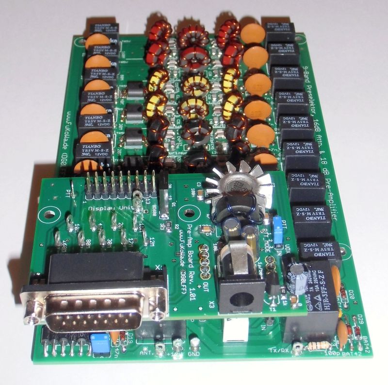
9-Kanal
Preselektor,
Bandpass-Filter mit Remote Steuerung
Bandpass-Filter mit Remote Steuerung
at moment not available
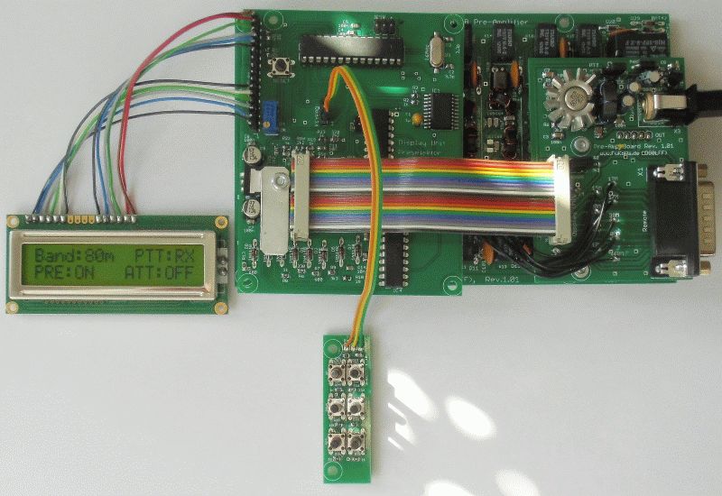
The controller show all system functions and actual status ofr band filter, pre amp, attenuator and TX/RX switching.
If the remote interface used, the controller show the actual status of remote lines and give you all informations what you need.
With this button panel is it easy to swtich the pre amp on or off and use the bypass function to analyze the recieve quality with or without bandpass filter
- button panel of controller
- 9 signal lines für bandpass filters are available at remote interface (low active, sub-d)
- 3 signal lines for Bypass /RX switching, pre amp and attenuator are at remote interface (low aktiv, sub-d)
- CAT Kommando Interface with real RS232 (sub-d), 4,8kBit/s, 8N1
The status of signal lines from remote interface have priority in the system. If one signal line active, then can this function not switch off by other control interfaces.
The Display show all status informations of the preselector include remote switching.
Modern receiver concepts works often with a wide RF frontend and a DSP system in ZF area. A preselector unit is often missing and this radio types have often problems to work with big antennas and stron RX signals. Specially the "All in One" magic boxes from popular manufacturers show this blocking and cross modulation effect in combination with big and full size antennas.
You can detect it at low bands in afternoon, when all stations work with more as "normal" TX power and QRM is bigger as the signal of the station.
The selection of filters is very strong and outband signals are supress. You can cehck this when you select at TRX a other and as at preselector. The S-meter is clos to standby position (S2-S3) and when you select the correct band filter you get S9+ for the same station.
If a filter setup wrong, you get the feeling your antenna is not connected.
The connetion point for controller installation is available at all shipped systems.
But a small modification is requiered for show the correct function of VOX system, when the controller unit is installed.
At pre amp pcb is a PTT/VOX jumper. This jumper need a permanetly connection between PTT pin and center pin. You can use a solder iron for that. Only when the connection exist, the controller display the TX/RX switching in VOX mode.
The controller pcb have a own power supply with a 5V linear voltage regulator. This board get the 12volts power from pre amp board over the 20 wire flat cable.
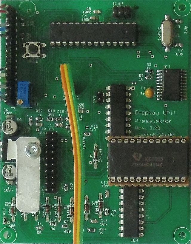
The diplay function of system status works with a voltage measurement at signal lines and translation for the display.
At this board is a UART lever converter from Maxxim for the serial interface installed. You don't need a additionally level converter to connect the system to your PC, its all built inside.
The display contrast can control with the blue poti close to display connector. The LCD display is a HD44780 kompatible 16x2 display with a KU0066 LCD controller. The connection between display and microcontroller are a 4 wire bus.
The hardware reset button for microcontroller reset is also close the display connection port. When you press this button, the controller will restart and switch to start setup.
The size of this board is 100 x 77mm.
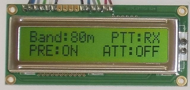
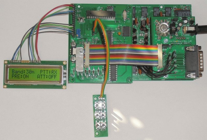
When you use a remote function, the display will show every time the actual setup of the preselector.
The 1. line show the selected band and TX/RX function, 2. line works for pre amp, remote information (@ or smiley) and attenuator.
When you use the remote interface, the display will show a smiley in middle of 2. line, when a filter is selected.
If you use the CAT interface, the display show a @ in the second line. This @ sign should show the active CAT status and the connetion to a PC.
The size of LCD are 80 x 36mm.
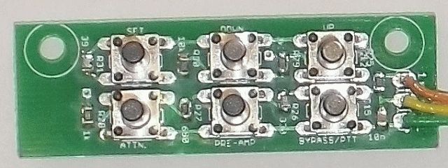
Down: switch to next lower band
Set: button for future function, now not used
PTT:
TX/RX switch, can use for Bypass function
PRE: 18dB pre amp on / offATT: 16dB attenuator on / off
The micro buttons are a long version with 12,5 length. In this button format can the button panel easy integrate behind front panels.
The pcb have two holes for screws to fix it behind front panel.
The size of button panel are 54 x 17mm.
The LCD display should installed at front side together with the button panel. Both pcb's match togeter at a front panel of a standard case for Eurocard pcb's
The installation in a case should in two layers. Bottom layer is the main filter board and the second layer are the pre-amp and the controller board.
==> Between filter board and controller unit should a metal plate as shielding between. The most standard cases have many milling lines to install the pcb in different positions. In one position between can sleve a thin alummina plate (100 x 80mm) and work as shield to protect the filter board for noise from controller board.
The main power lines of the controller board have emv filters and capacitors close to the integrated circuits for suppress "man made noice" but the TRX should resceive very small signals and it is better when you do whats possible. :-)